FOUR FORCES OF FLIGHT

Four Forces Of Flight
The science of aerodynamics deals with the motion of air and the forces acting on bodies moving relative to the air. When you study aerodynamics, you are learning about why and how an airplane flies. Although aerodynamics is a complex subject, exploring the fundamental principles which govern flight can be an exciting and rewarding experience. The challenge to understand what makes an airplane fly begins with learning the four forces of flight.
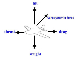
During flight, the four forces acting an the airplane are lift , weight , thrust and drag. Lift is the upward force created by the effect of airflow as it passes over and under the wing. The airplane is supported in flight by lift. Weight which opposes lift, is caused by the downward pull of gravity. Thrust is the forward force which propels the airplane through the air. It varies with the amount of engine power being used. Opposing thrust is drag, which is a backward or retarding, force which limits the speed of the airplane. In un-accelerated flight, the four forces are in equilibrium. Un-accelerated flight means that the airplane is maintaining a constant airspeed and is neither accelerating nor decelerating.
In straight and-level , un-accelerated flight, lift is equal to the directly opposite weight and thrust is equal to and directly opposite drag. Notice that the arrows which represent the opposing forces are equal in length, but all four arrows are not the same length. This indicates that all four forces are not equal but that the opposing forces are equal to each other.
The arrows which show the forces acting on an airplane are often called vectors. The magnitude of a vector is indicated by the arrow’s length, while the direction is shown by the arrow’s orientation. When two or more forces act on an object at the same time, they combine to create a resultant.
When vertical and horizontal forces are applied, as shown on the left, the resultant acts in a diagonal direction. As shown on the right, the resultant of two opposing forces, which are equal in magnitude, is zero.
Lift is the key aerodynamic force. It is the force which opposes weight. In straight-and-level, in-accelerated flight, when weight and lift are equal, an airplane is in a state of equilibrium. If the other aerodynamic factors remain constant, the airplane neither gains nor loses altitude.
When an airplane is stationary on the ramp, it is also in equilibrium, but the aerodynamic forces are not a factor. In calm wind conditions, the atmosphere exerts equal pressure on the upper and lower surfaces of the wing movement of air about the airplane, particularly the wing, is necessary before the aerodynamic force of lift becomes effective. Knowledge of some of the basic principles of motion will help you to understand the force of lift.
Newton’s Laws of Force & Motion

Sir Issac Newton
In the 17th century, Sir Isaac Newton, a physicist and mathematician presented principles of motion which, today; help to explain in creation of lift by an airfoil. Newton’s three laws of motion are as follows.
Newton’s first law : A body at rest tends to remain at rest, and a body in motion tends to remain moving at the same speed and in the same direction. For example, an airplane at rest on the ramp will remain at rest unless a force is applied which is strong enough to overcome the airplane’s inertia.
Newton’s second law: When a body is acted upon by a constant force, its resulting acceleration is inversely proportional to the mass of the body and is directly proportional to the applied force. This law may be expressed by the formula: [Force = mass x acceleration (F=ma)]
Newton’s third law : For every action there is an equal and opposite reaction. This principle applies whenever two things act upon each other, such as the air and the propeller, or the air and the wing of an airplane.
BERNOULLI’S PRINCIPLE

Bernoulli
Daniel Bernoulli, a Swiss mathematician, expanded on Newton’s idea and further explored the motion of fluids I his 1783 publication Hydrodynamics. It was in this text that Bernoulli’s equation, which describes the basic principle of airflow pressure differential, first appeared. Bernoulli’s principle, simply stated, says, “as the velocity of a fluid (air) increases, its internal pressure decreases.’ Bernoulli’s principle is derived from Newton’s second law of motion which states the requirement of an in balanced force (in this case, pressure) to produce an acceleration (velocity change).
One way you can visualize Bernoulli’s principles to imagine air flowing through a tube which is narrower in the middle than at the ends. This type of device is usually called a venturi.
As the air enters the tube, it is traveling at a known velocity and pressure. When the airflow enters the narrow portion, the velocity increases and the pressure decreases. Then, as the wider portion, both the velocity and pressure return to their original values. Throughout this process, the total energy of the air stream is conserved. An increase in velocity (kinetic energy) is accompanied by a decrease in static pressure (potential energy).
List of an Aircraft Depend on
1. Air density
2. Velocity
3. Shape of the wing
4. Angle of attack
5. Wing area
Three Axes of Flight
1. Longitudinal Axis (Rolling)
2. Pitching (Lateral Axis)
3. Vertical Axis (Yoking)
BALANCE

An important consideration when designing a longitudinally stable airplane is the balance between the center of gravity and the center of pressure of the wing. The center of pressure is a point along the wing chord line where lift is considered to be concentrated. For this reason, the center of pressure is sometimes referred to as the center of lift. On a typical cambered wing, this point along the chord line changes position with different flight attitudes. It moves forward as angle of attack increases and after as angle of attack decreases. As a result, pitching tendencies created by the position of the center of pressure in relation to the CG vary.
For example, with a high angle of attack and the center of pressure in a forward position 9closer to the CG) the nose-down pitching tendency is decreased. The reverse is true as the angle of attack is decreased and the center of pressure moves further after of the CG.
To maintain balance, and aid longitudinal stability, most aircraft are designs so that, during normal operations, the center of pressure remains after of the center of gravity.
CENTER OF GRAVITY POSITION
The position of the center of gravity (CG), which is determined by the distribution of weight either by design or by the pilot, can also affect the longitudinal stability of an airplane. If the CG is too far forward, the airplane is very nose heavy; if the CG is too far after, the airplane may become tail heavy. To achieve longitudinal stability, most airplanes are designed so they’re slightly nose heavy. This is accomplished during the engineering and development phase by placing the center of gravity slightly forward of the center of pressure.
Your control over CG location is largely determined by what you put into the airplane, and where you put it. This includes the weight of items such as fuel, passengers, and baggage. For example, if you load heavy baggage into after baggage compartment, it might cause the CG to shift to an unfavorable position which can result in severe control problems. As you might expect, for an airplane to be controllable during flight, the CG must be located within a reasonable distance forward or after of an optimum position. All airplanes have forward and after limits for the position of the CG. The distance between these limits is the CG range.
HORIZONTAL STABILIZER
When the airplane is properly loaded, the CG remains forward of the center of pressure and the airplane is slightly nose heavy. The nose-heavy tendency is offset by the position of the horizontal stabilizer, which is designed with a negative angle of attack. This produces a downward force, or negative lift on the tail, to counteract the nose heaviness. The downward force is called the tail-down force, and is the balancing force in most flight conditions.
Longitudinal stability is also aided by the horizontal stabilizer which, due to a negative angle of attack, produces a downward force to counteract nose down tendencies.
Additional forces are exerted on horizontal tail surfaces of most aircraft by down-wash from the propeller and the wings. T-tail designs are not subject to the same down-wash effect, simply because the horizontal tail surface is above most, or all, of the down-wash. With the exception of T-tail airplanes, the strength of the downward force on the horizontal stabilizer is related to angle of attack, speed of the airplane, and power setting in single engine propeller driven airplanes. Any variance in the strength of the down-wash, such as a power change, affects the horizontal tail’s contribution to longitudinal stability
ROTARY WING THEORY

Before we look at how they fly, we had better identify the different types of rotorcraft. Rotorcraft can be categorized into the following types:
· 1. Gyroplanes or Gyrocopters
· 2. Helicopters
· 3. Compound Helicopters
· 4. Tilt Wing/Tilt Rotar Aircraft or Convertiplanes.
HELICOPTER ADVANTAGES & DISADVANTAGES
When compared to conventional aircraft, the helicopter has the following advantages:
· 1. It is capable of vertical ascent and descent
· 2. It can hover
· 3. It can fly in any direction in any place
· 4. Take off and landing can be carried out in an area a little larger than the aircraft
· 5. No runway is required
· 6. The surface of the landing area, if reasonably level, is relatively unimportant
· 7. Landing can usually be made under conditions of engine failure
Disadvantages:
· 1. It has a comparatively low forward speed compared to fixed-wing aircraft
· 2. Lifting efficiency falls off rapidly with increase in altitude
· 3. It requires a power unit approximately twice a powerful as the conventional aircraft
· 4. It can, in its conventional form, be susceptible to loss of control in strong cross or tail winds
Helicopter configurations
There are a number of configurations of helicopter design; the choice will depend on several factors:
· 1. Size and weight, which determines the power and number of blades required
· 2. Method of achieving control and overcoming torque reaction
· 3. The role of the helicopter
Configurations which have been used in helicopter design are:
· 1. Single Rotor (conventional tail rotor)
· 2. Single Rotor (NOTOR)
· 3. Single Rotor (Fenestrom)
· 4. Tandem Rotor intermeshing
· 5. Tandem Rotor Non-Intermeshing
· 6. Synchropter
· 7. Side By Side
· 8. Coaxial
· 9. X-Wing
